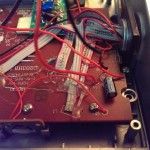
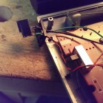
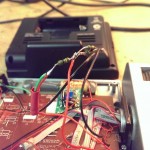
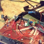
The two 1.5V AA batteries in my radio (DCF77) alarm clock were empty and I didn’t want to change them with new ones. I preferred a solution with a DC wall adaptor.
The alarm clock has a built in projector, which can project the current time to a wall. This projector works, if the light button on the clock is pressed, for 5 seconds. If you want the projector to light all the time, an external DC source (3V, 100mA) is needed. With a switch on the case of the clock, the projector can be enabled durable (if the external DC source is connected).
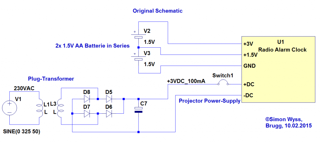
The Clock needs a 3V and 1.5V Power supply from the batteries. The 1.5V are supplied from between the two batteries.
Original Clock Schematic (the clock itself is a blackbox):
Modified Schematic:
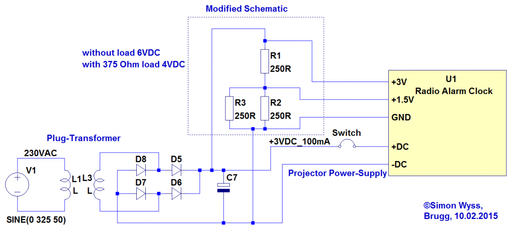
A problem is that without load, the transformer has an output-voltage of 6V. With 500 Ohms load, the voltage drops to 4V. If the projector is on, the transformer voltage drops to 2.8V. The challenge is, to provide the 3V and 1.5V with the simplest possible circuit. (Voltage regulators would be a solution, but to luxury for such a modification)
To serve 1.5V from the DC-Wall-Transformer, I experimented with different voltage dividers. I recognized that if the 1.5V voltage was higher than 1.5V, the clock didn’t work anymore. But it was no problem, if the 3V voltage was higher than 3V.
A 1/2 voltage divider with 2.7k Ohm resistors had a too high impedance for the clock (the 1.5V dropped to low and the clock didn’t turn on)
A 1/2 voltage divider with 250 Ohm Resistors worked, but only, if the projector was permanently turned on.
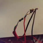
The final solution was a voltage divider with 250 Ohms to 125 Ohms. The 1.5V voltage is below 1.5V at 1.3V with 4V input voltage and at 1V with 3V input Voltage. But the alarm clock works fine with this solution. (It works with projector turned on and off)
