ATX Power Supply 18V and 30V Modification

My first attempt to build a power supply capable of 10A @ 30V for my 2x100W Class D-Amp was not successful, because I only reached 10A@ 24V. My next idea was, to modify an ATX-Computer-Power-Supply from 12V to 18V and connect a unmodified (original) ATX-Power-Supply with a modified 18V to reach 30V and 10A.

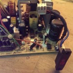
In this post is the modification from of the ATX-Powersupply to output 10A @ 18V described.

Attention: Don’t modify a Power-Supply if you aren’t trained with Low-Voltage! I don’t guarantee, that the schematic of the Power-Supply is correct! If the Power-Supply is faulty mains-voltage can reach the DC-Output! Capacitors can stay charged to 325V after disconnecting the power-supply from mains-voltage. You do all modifications at your own risk! I am not responsible for damages, fire and injuries!

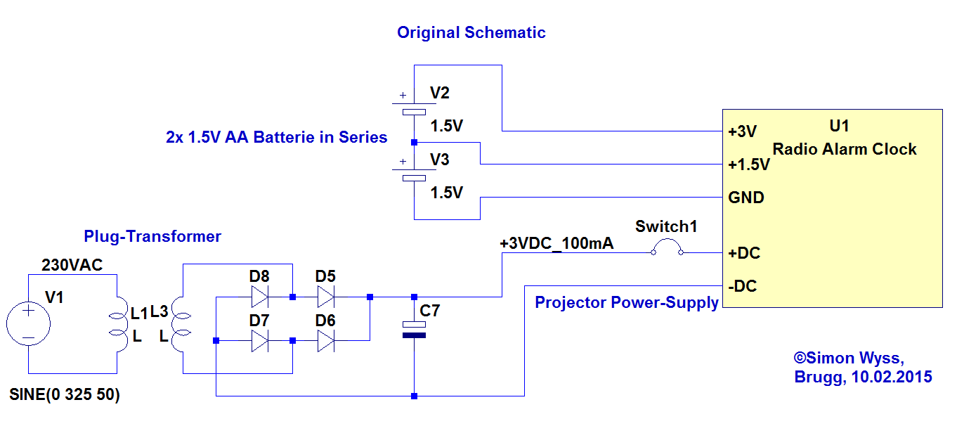
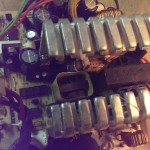
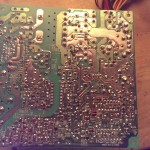
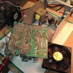
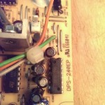
Original Schematic of the “DPS-240EP” ATX-Power-Supply (read out from circuit board):ATX DPS-240EP

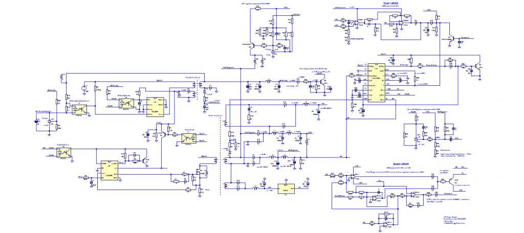
I did a lot of steps to the final version of the modification. The first idea was, to cheat the control-IC (DNA1002)of the power-supply. Unfortunately I didn’t found a datasheet of this IC. It seems, that it is a custom IC for the power-supply manufacturer “Delta”.  From schematic “drafts” of this IC I recognized the voltage-monitoring pins for 5, 12 and -12V. Next I connected this pins with voltage regulators fix to the needed voltages.

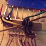
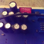
The voltage Regulation of the power-supply is done with a tl431 voltage reference. I replaced the on-board potentiometer with an own and could adjust the 12V rail up to 18V. Attention, before this voltage modification I replaced the old electrolyte capacitors on the 12V rail and 5V rail with 25V and 10V types.

Sadly now the power-on of the circuit didn’t worked proper no more. So I decided to go away from the control circuit DNA1002 and bridge the circuit at the required points. (As I understand the circuit, there is no over current monitoring with shunts. The DNA1002 just monitors the voltage, and in case of an overcurrent [or empty capacitor connected] the voltage drop for a short moment is recognized and the power-supply shut down.

Attention, the modification has a very high current limit: The IC UC3845 on the primary side has a 0.18 Ohm shunt, which limits the primary (325V) current to max. 1V over the shunt (1V/0.18 = 5.5A). The secondary current can be very high (5.5A*325V = 1.78kW !!!). It would be better, if the primary shunt is enhanced to 1 Ohm.

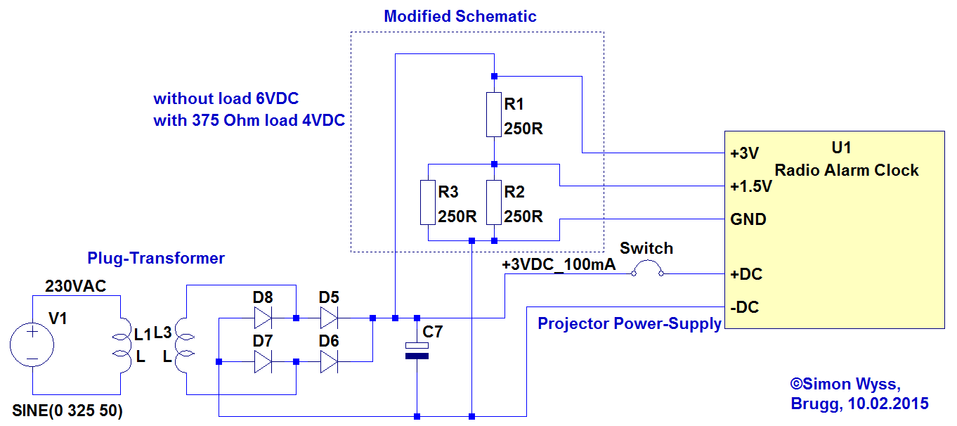
Modified Schematic (modifications in doted circles):ATX DPS-240EP

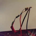
That I could connect this power-supply with another ATX power-supply in series I removed the connection from the secondary GND to the primary “protective earth” (PE) (german: Schutzleiter). Attention, if the power-supply is faulty mains voltage on the secondary would no longer kill the fuse!

iROX Radio Alarm Clock external Power-Supply

The two 1.5V AA batteries in my radio (DCF77) alarm clock were empty and I didn’t want to change them with new ones. I preferred a solution with a DC wall adaptor.

The alarm clock has a built in projector, which can project the current time to a wall. This projector works, if the light button on the clock is pressed, for 5 seconds. If you want the projector to light all the time, an external DC source (3V, 100mA) is needed. With a switch on the case of the clock, the projector can be enabled durable (if the external DC source is connected).

The Clock needs a 3V and 1.5V Power supply from the batteries. The 1.5V are supplied from between the two batteries.

Original Clock Schematic (the clock itself is a blackbox):

Radio Alarm Clock original schematic

Modified Schematic:

Radio Alarm Clock modified schematic

A problem is that without load, the transformer has an output-voltage of 6V. With 500 Ohms load, the voltage drops to 4V. If the projector is on, the transformer voltage drops to 2.8V. The challenge is, to provide the 3V and 1.5V with the simplest possible circuit. (Voltage regulators would be a solution, but to luxury for such a modification)

To serve 1.5V from the DC-Wall-Transformer, I experimented with different voltage dividers. I recognized that if the 1.5V voltage was higher than 1.5V, the clock didn’t work anymore. But it was no problem, if the 3V voltage was higher than 3V.

A 1/2 voltage divider with 2.7k Ohm resistors had a too high impedance for the clock (the 1.5V dropped to low and the clock didn’t turn on)

A 1/2 voltage divider with 250 Ohm Resistors worked, but only, if the projector was permanently turned on.

The final solution was a voltage divider with 250 Ohms to 125 Ohms. The 1.5V voltage is below 1.5V at 1.3V with 4V input voltage and at 1V with 3V input Voltage. But the alarm clock works fine with this solution. (It works with projector turned on and off)

Netgear GS608 v2 Repair

Netgear GS608 v2
Netgear GS608 v2

The LAN connection from a computer to my home-network stopped working from one day of the other. First I thought, it could have to do with the network-lan-card in the specific computer. Sadly I did no detailed test and did not locate the problem exactly.

Weeks later I realized, that other computers in the network couldn’t connect too over LAN. Next I updated the router (FritzBox 7390 ) to the newest firmware version (6.25). This didn’t solved the problem. If a Computer was directly over LAN connected to the FritzBox, everything worked. So the only bad thing between could be the Netgear 8 Port Switch GS608 v2. Strange was, that the LEDs in the Switch light up, if a device was connected by cable.

Because the switch is capable of 1Gbit/s it has two LEDs per Port (green an orange). If a 100Mbit/s device is connected, the orange LED shines. If a faster, 1Gbit/s device is connected, the green LED shines.

I recognized, that the FritzBox (capable of 1Gbit/s) was detected by the switch as 100Mbit/s = slow = orange light. My Laptop could only connect every 10 seconds for about one second. Really strange.

If I connected a 100Mbit/s Switch between my Laptop and the faulty Netgear Switch my connection to the network worked!

It turned out, that 100Mbit/s connections through the Netgear Switch worked, but faster connections caused problems.

Also only a number of devices were working properly, if more than 4 devices were plugged in, the later added devices couldn’t establish a connection – the LEDs of their ports stayed dark.

I didn’t know, what was happen with the router, which worked fine for 7 years. I searched the web and found randomly a post about a fix for this router https://tinajalabs.wordpress.com/2011/03/20/netgear-gs605-v2-fix/. The writer recognized, that his internet-connection was slow and searched the web and found, that bad capacitors in the switch can cause the problem.

I opened up the switch (4-Torx screws on the bottom under anti-slip pads) and saw the two blew up electrolyte capacitors. A third electrolyte capacitor was fine.

I unsoldered the capacitors and replaced them by two with identical capacity (1000uF) and voltage (10V) rating. (Mine are only rated 85°C and not 105°C like the old ones, but I think, they should last at least some years).

Problem solved, everything works again at full speed, as it should. I think this is a product more with planned obsolescence. Two small parts can make the whole device waste. And not everyone knows who two change electrolyte-capacitors.


Power supply for 2x100W Class-D Audio Amp

In my first semester of the EIT study at the FHNW in Windisch (Switzerland) I built in the Module “Basic Laboratory (of Electrical Engineering)” a Class-D audio amp. This amp was developed by Stefan Wicki at FHNW http://wictronic.ch/CDAMP.htm. The AMP needs a supply voltage between 12V 30V. Maximum Sinus-Power is 2x100W, 2x 200W Peak. Following current is needed:  200W/30V = 6.6A.

I had no power-source, which could deliver 7A @ 30V, so I decided to build my own. The first attempt was to use a toroidal transformer with following data: prim. 1x 230V AC, sec. 2x 19V 2x 5A, sec. 2x 18V 1A. I hooked up both of the powerful 5A 19V windings in parallel. The two 19V windings had a voltage-difference of about 1V. This is too much for direct in parallel connecting. There would be a high compensation-current of some Amperes from one winding to the other.

That the Load-Current is spitted equal to both windings I added a circuit, which distributes the load-current equal on both windings:

Toroid transformer windings parallel schematic

First, the both windings are separate rectified and filtered with capacitors. Then each DC current flows through a 0.1Ohm shunt. The currents are measured over the shunts with an Operation Amplifier and compared. The winding with the higher voltage has a Power-MOSFET in its DC-Path. This MOSFET is regulated with the OPA, that always the same amount of current flows through each shunt and therefore also through each winding.

The OPA is supplied over a DC-DC convert (which is galvanically isolated), which is supplied by the 2x18V windings in series. The GND of the OPA circuit is the the lower point of the two shunts.

The current sharing circuit works really well. Both windings are always loaded with the same current. Unsatisfied was, that the output voltage of this transformer solution was “only” about 25V (19V*sqrt(2) – 1.4V [Rectifier Drop] = 25V). The Class-D-Amp would take for the full 2x100W Power, 30V input voltage.

The circuit was built on a wood plate:

The Audio Amp worked very well with this transformer supply, but with almost full audio level of the pre-amp (Input Signal – 0db to – 8dB), the audio was not clear as before, and I think the Audio-Amp clipped, because of the too low supply voltage. (but this was until now not measured).

The Next step is to build a Power-Supply capable of minimum 7A @ 30V.

Later thoughts were, that the distorted audio at -8dB could be the total harmonic distortion, which could be already audible at this power-level: 100W*-8dBV = 100W*0.398 = 40W.

THD
THD

User-Scripts for Browsers

User-Scripts are JavaScript Scripts for many Browsers. With those, you can modify websites locally in your browser.

Own Scripts, that I have written:
Farnell Online-Shop Switzerland (ch.farnell.com): language set to German, accept cookies, set cursor to search field: http://www.simonwyss.me/userscripts/farnell_1.user.js