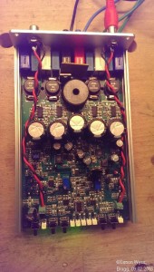
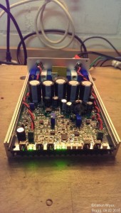
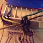
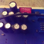
In my first semester of the EIT study at the FHNW in Windisch (Switzerland) I built in the Module “Basic Laboratory (of Electrical Engineering)” a Class-D audio amp. This amp was developed by Stefan Wicki at FHNW http://wictronic.ch/CDAMP.htm. The AMP needs a supply voltage between 12V 30V. Maximum Sinus-Power is 2x100W, 2x 200W Peak. Following current is needed: 200W/30V = 6.6A.
I had no power-source, which could deliver 7A @ 30V, so I decided to build my own. The first attempt was to use a toroidal transformer with following data: prim. 1x 230V AC, sec. 2x 19V 2x 5A, sec. 2x 18V 1A. I hooked up both of the powerful 5A 19V windings in parallel. The two 19V windings had a voltage-difference of about 1V. This is too much for direct in parallel connecting. There would be a high compensation-current of some Amperes from one winding to the other.
That the Load-Current is spitted equal to both windings I added a circuit, which distributes the load-current equal on both windings:
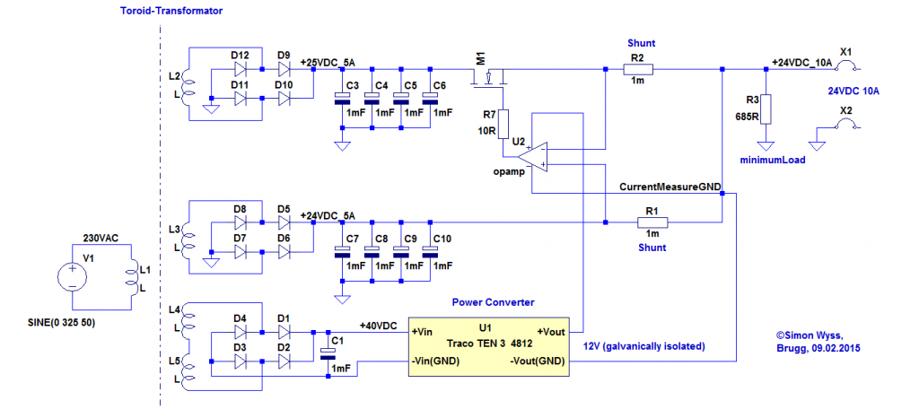
First, the both windings are separate rectified and filtered with capacitors. Then each DC current flows through a 0.1Ohm shunt. The currents are measured over the shunts with an Operation Amplifier and compared. The winding with the higher voltage has a Power-MOSFET in its DC-Path. This MOSFET is regulated with the OPA, that always the same amount of current flows through each shunt and therefore also through each winding.
The OPA is supplied over a DC-DC convert (which is galvanically isolated), which is supplied by the 2x18V windings in series. The GND of the OPA circuit is the the lower point of the two shunts.
The current sharing circuit works really well. Both windings are always loaded with the same current. Unsatisfied was, that the output voltage of this transformer solution was “only” about 25V (19V*sqrt(2) – 1.4V [Rectifier Drop] = 25V). The Class-D-Amp would take for the full 2x100W Power, 30V input voltage.
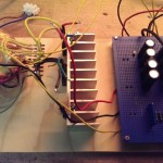
The circuit was built on a wood plate:
The Audio Amp worked very well with this transformer supply, but with almost full audio level of the pre-amp (Input Signal – 0db to – 8dB), the audio was not clear as before, and I think the Audio-Amp clipped, because of the too low supply voltage. (but this was until now not measured).
The Next step is to build a Power-Supply capable of minimum 7A @ 30V.
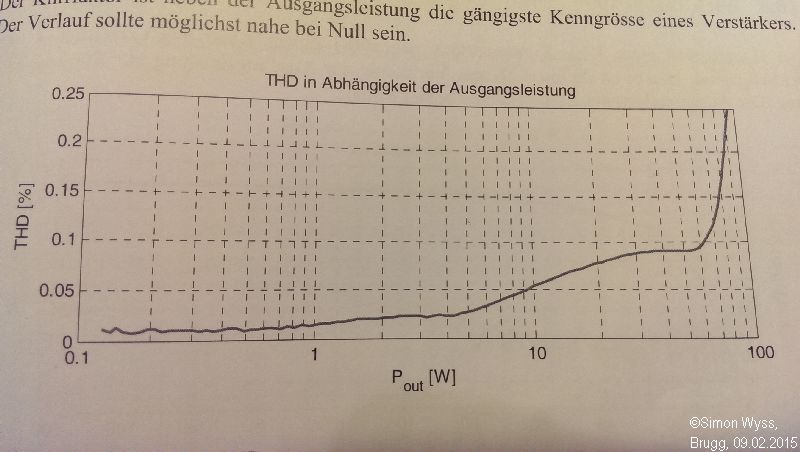
Later thoughts were, that the distorted audio at -8dB could be the total harmonic distortion, which could be already audible at this power-level: 100W*-8dBV = 100W*0.398 = 40W.
