Server Power Supply Pinout

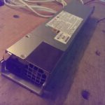
While dumpster diving the electronic scrap I find always interesting parts.

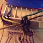
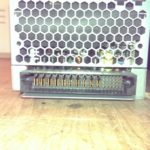
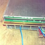
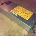
Last week I found some rack server with hot swap power supply. I removed the power supplies and reverse engineered the pinout of them.

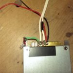
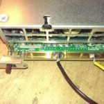
On the following pictures you see the power supply and their pinout.

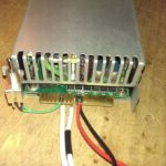
At the moment there are only the power and power-on pins known. The other unknown pins could be SPI or I2C for handling status information of the power supply or to regulate the cooling fan speed.

The power-on pins are often the shorter pins. They have to be shorter, because if the power supply is hot plugged, they should connect last after all other pins are already connected.

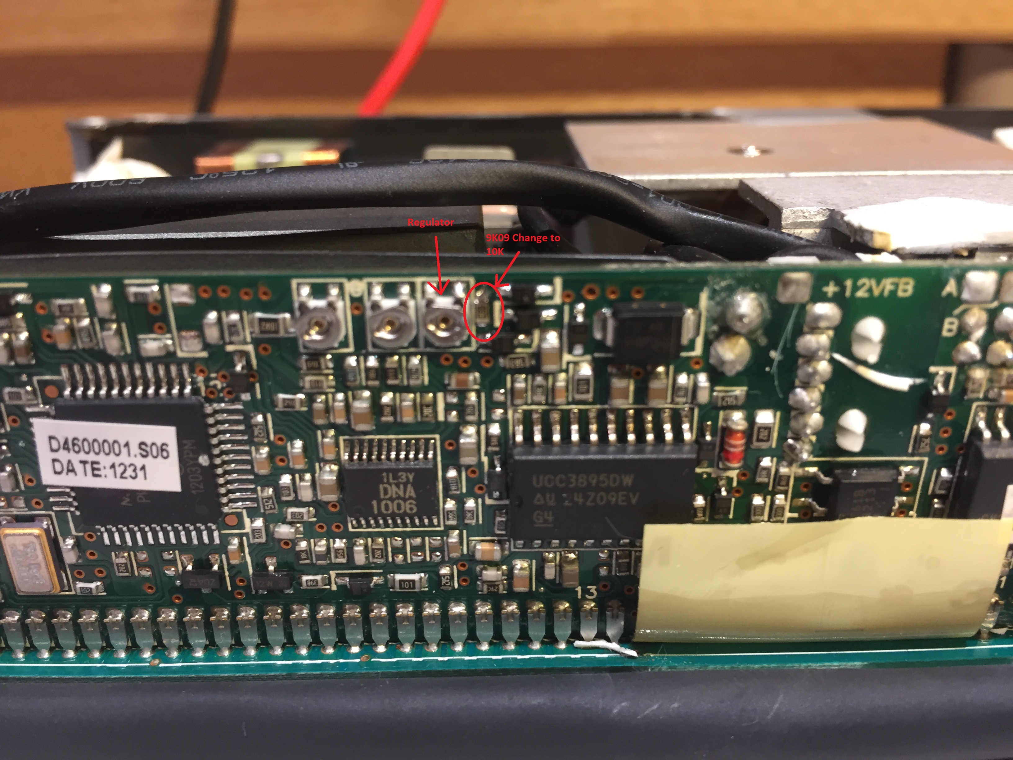
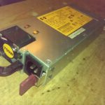
EDIT (2017-10-11): By courtesy of JP Peiffer (Belgium)
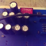
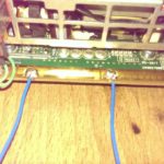
He found a way to modify the HP DPS-460EB A (see below) to output 13.5V instead of 12V.

Modification: Change 9K09 resistor (on the right of the three potentiometers) on the piggyback controller board to 10k.
Now you can adjust the output voltage with the top right potentiometer to max 13.62V. At higher voltages, the overvoltage limiter kicks in. (IC/location of the limiter must be found).

To get safe startup, set the output voltage only to 1.5V. Other wise it hangs sometimes when booting, due to overshoots.

HP DPS-460EB A 13.6V Modification

Power Supply Emerson 7001540-J000
+12V 40A
+5.1V 30A
3.36V STBY 0.45A

Pinout_Emerson_7001540-J000

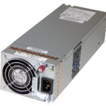
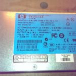
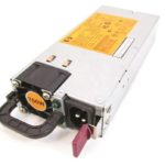
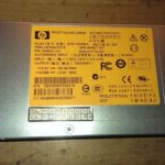
Power Supply HP DPS-460EB A
+12V 38.3A
12V STBY 2.5A

Pinout_HP_DPS-460_HP_DSPS-750

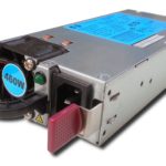
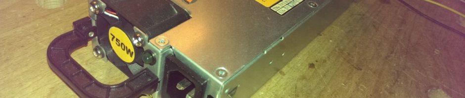
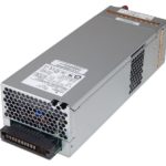
Power Supply HP DPS-750RB A
+12V 62.5A
+12V STBY 2.5A

Resistor Value in Picture “DC Plug Top View”: 100 Ohms

Pinout_HP_DPS-460_HP_DSPS-750

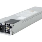
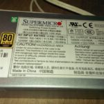
Power Supply Supermicro PWS-1K21P-1R
+12V 100A
+5V STBY 4A

Pinout_Supermicro_PWS-1K21P-1R

Power supply for 2x100W Class-D Audio Amp

In my first semester of the EIT study at the FHNW in Windisch (Switzerland) I built in the Module “Basic Laboratory (of Electrical Engineering)” a Class-D audio amp. This amp was developed by Stefan Wicki at FHNW http://wictronic.ch/CDAMP.htm. The AMP needs a supply voltage between 12V 30V. Maximum Sinus-Power is 2x100W, 2x 200W Peak. Following current is needed:  200W/30V = 6.6A.

I had no power-source, which could deliver 7A @ 30V, so I decided to build my own. The first attempt was to use a toroidal transformer with following data: prim. 1x 230V AC, sec. 2x 19V 2x 5A, sec. 2x 18V 1A. I hooked up both of the powerful 5A 19V windings in parallel. The two 19V windings had a voltage-difference of about 1V. This is too much for direct in parallel connecting. There would be a high compensation-current of some Amperes from one winding to the other.

That the Load-Current is spitted equal to both windings I added a circuit, which distributes the load-current equal on both windings:

Toroid transformer windings parallel schematic

First, the both windings are separate rectified and filtered with capacitors. Then each DC current flows through a 0.1Ohm shunt. The currents are measured over the shunts with an Operation Amplifier and compared. The winding with the higher voltage has a Power-MOSFET in its DC-Path. This MOSFET is regulated with the OPA, that always the same amount of current flows through each shunt and therefore also through each winding.

The OPA is supplied over a DC-DC convert (which is galvanically isolated), which is supplied by the 2x18V windings in series. The GND of the OPA circuit is the the lower point of the two shunts.

The current sharing circuit works really well. Both windings are always loaded with the same current. Unsatisfied was, that the output voltage of this transformer solution was “only” about 25V (19V*sqrt(2) – 1.4V [Rectifier Drop] = 25V). The Class-D-Amp would take for the full 2x100W Power, 30V input voltage.

The circuit was built on a wood plate:

The Audio Amp worked very well with this transformer supply, but with almost full audio level of the pre-amp (Input Signal – 0db to – 8dB), the audio was not clear as before, and I think the Audio-Amp clipped, because of the too low supply voltage. (but this was until now not measured).

The Next step is to build a Power-Supply capable of minimum 7A @ 30V.

Later thoughts were, that the distorted audio at -8dB could be the total harmonic distortion, which could be already audible at this power-level: 100W*-8dBV = 100W*0.398 = 40W.

THD
THD