While dumpster diving the electronic scrap I find always interesting parts.
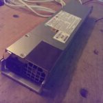
Last week I found some rack server with hot swap power supply. I removed the power supplies and reverse engineered the pinout of them.
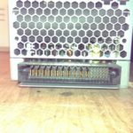
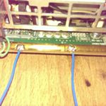
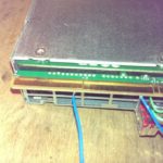
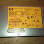
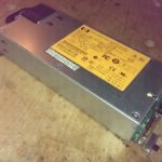
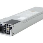
On the following pictures you see the power supply and their pinout.
At the moment there are only the power and power-on pins known. The other unknown pins could be SPI or I2C for handling status information of the power supply or to regulate the cooling fan speed.
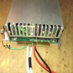
The power-on pins are often the shorter pins. They have to be shorter, because if the power supply is hot plugged, they should connect last after all other pins are already connected.
EDIT (2017-10-11): By courtesy of JP Peiffer (Belgium)
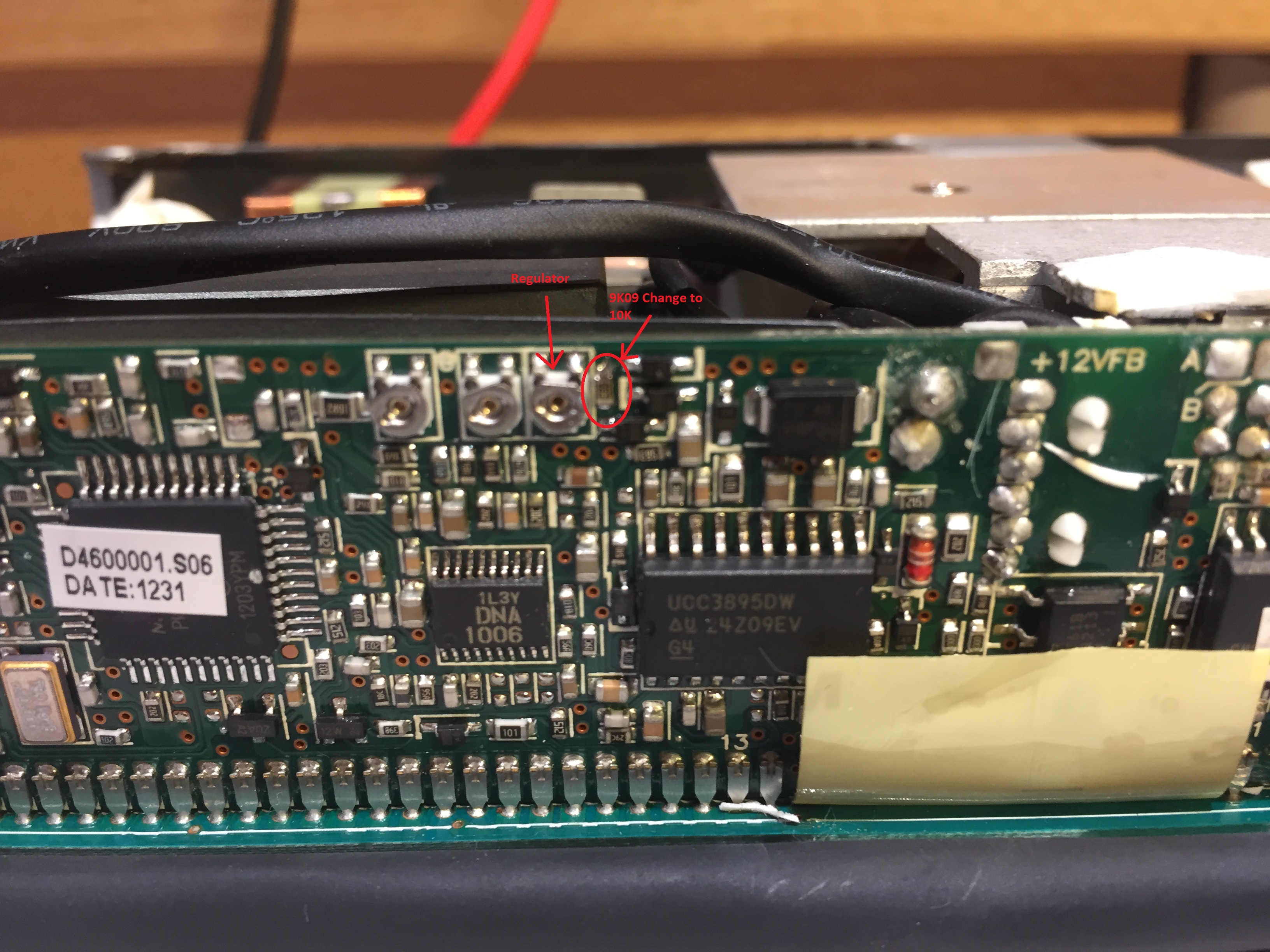
He found a way to modify the HP DPS-460EB A (see below) to output 13.5V instead of 12V.
Modification: Change 9K09 resistor (on the right of the three potentiometers) on the piggyback controller board to 10k.
Now you can adjust the output voltage with the top right potentiometer to max 13.62V. At higher voltages, the overvoltage limiter kicks in. (IC/location of the limiter must be found).
To get safe startup, set the output voltage only to 1.5V. Other wise it hangs sometimes when booting, due to overshoots.
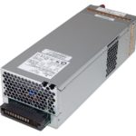
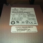
Power Supply Emerson 7001540-J000
+12V 40A
+5.1V 30A
3.36V STBY 0.45A
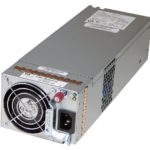
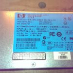
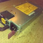
Power Supply HP DPS-460EB A
+12V 38.3A
12V STBY 2.5A
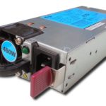
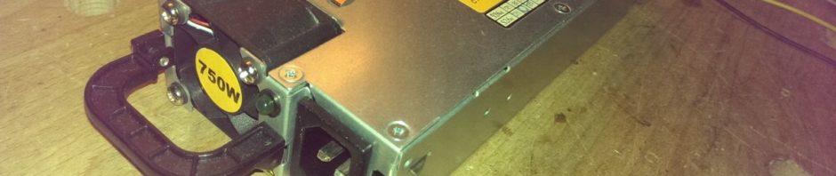
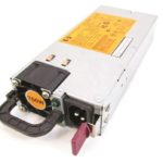
Power Supply HP DPS-750RB A
+12V 62.5A
+12V STBY 2.5A
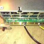
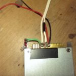
Resistor Value in Picture “DC Plug Top View”: 100 Ohms
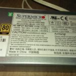
Power Supply Supermicro PWS-1K21P-1R
+12V 100A
+5V STBY 4A
Hello, for HP_DPS-460_HP_DSPS-750 i can see a resistor in your photos. How is connected?
I connect pin 1 and 4 but power supply does not start. The power supply is OK.
Thank you.
Hi Manuel
The switch connects with a 100 ohm series resistor pin 1 and 4 of the power supply.
I tested again if the power supply switches on without the resistor (with a direct connection of pin 1 and 4) and it worked.
But it could be more stable, if you use a resistor. The resistor shouldn’t have more than 100 ohms else it won’t work.
Simon
Simon hello,I tried the 100 ohm resistor on 1 and 4 would not come on that way even tried another 100 ohm resistor same issue but jumping 1 and 4 and it comes on??
Hi Simon, thank you for you reply.
YES ! 🙂 i have started it two times without the resistor. Later i will use a resistor to try it again and see if starts allways.
But i have to connect pins 1 and 4 for various seconds until PS starts. Is it normal?
Manuel
My power supplies start immediately (power on LED light up) but the fan starts slowly (some seconds later).
Ok. Now all is working fine. Yes, power led start inmediately, and 12V DC.
Thank you for your help.
0n the dps 750 picture i see a green resistor near the switch. fan control? explain please
Hi dom milan
The resistor is not for fan control. I remember that the power supply won’t start with a short circuit between pin 1 and 4. So I added a 100 Ohm Resistor (or 300 Ohm) in series with the switch.
The pinout is available in the pdf. (Link here again: https://simonwyss.me/blog/wp-content/uploads/2017/02/Pinout_HP_DPS-460_HP_DSPS-750.pdf)
For power on connect both Pon pins (pin 1 and 4 with a 100 Ohm resistor in between
Hi Simon, thanks for sharing!
I have two of the dps-750rb a and I’d like to connect them in series to have 24v output.
I can see the chassis and mains ground are connected to the output gnd.
Do you think it is possible to connect them in series in a reasonable safe way?
Hi Pascal
To remove the GND connection of a power supply is never a safe solution. But if you know what your doing it should work 😉
I have already tried such a modification with other power supplies. It can work, but the voltage control is not always as stable as before.
You can find more information on how to mod server power supplies in the following forum:
https://www.rcgroups.com/forums/showthread.php?1292514-How-to-convert-Server-Power-Supplies
https://www.rcgroups.com/forums/showthread.php?1170241-Using-two-power-supplies-for-higher-voltage-capacity-chargers-safety-issues
I like to know, if you make progress.
Hello, any info on how to change the fan speed HP DPS750rb?
Hi Charles
I didn’t try it. However, I got some ideas:
These server power supplies have normally a I2C interface to control some parameters and read status registers.
There is a standard calld PMbus. The physical layer is I2C and the registers and higher level definitions are documented in the PMbus standard. As I know its open and accessible for any one:
First you have to know, which pins of the power supply are the I2C Pins. You could find them by try and error :-). You would have to connect always two pins of the powersupply to your I2C Master (an arduino or other microcontroller). But this are a lot of possible combinations. Don’t forget to add a 4.7k Ohms Resistor as pullup to 3.3V on each line (data SDA and clock SCL).
Please let me know, if you have found the SDA and SCL lines and if you got the PMBus fan control working.
https://en.wikipedia.org/wiki/Power_Management_Bus
http://pmbus.org/Home
http://www.pmbus.org/Assets/Present/Using_The_PMBus_20051012.pdf
https://www.i2c-bus.org/pmbus/
Information about fan control on the PMBus:
http://pmbus.org/Assets/PDFS/Public/PMBus_App_Profile_ACDC_Server_Power_rev_1_2_20120416.pdf
Hi,
I have nought a DPS750RB. I would lioke change the output power from 12v to 13,8v or 13,6v
How can I do that ?
I have seen to change the SMD resistor from 9k to 10k just near the variator and soldier pin 1 and 4
Is it all I must do to adapt the output power?
Anybody can help me ?
Regards
Paul
Hi Paul
I didn’t tried this modifications by my self. A reader of my blog suggests to do it, like it is described in my blog above.
It works on the DPS-460. I don’t know, if the DPS-750 has the same controller circuit.
Change 9K09 resistor (on the right of the three potentiometers) on the piggyback controller board to 10k.
Pleas let me know, if it works. I will add your feedback to my blog, if allowed (with reference to you).
Regards,
Simon
Dps 750RB while looking to do 13+V mod for this supply I found the controller is very similar with many of the same chips but perhaps a newer revision. I also found that turning the same potentiometer as for the 460w unit got me to 12.85V. My guess is if one could Identify the resistor hooked directly to this pot and replace it with a resistor about 10% higher, you might be able to get over 13v.
It worked for me the Power Supply HP DPS-460EB A case. Thanks…
Hi, I have Lite-On PS-2122-8L1 server power supply. Which iam trying to power it on without server. But iam unable to do it as there is no information regarding this psu or anything related to this psu. Do you have any info regarding this. Or any directions where i can find info for the same. Thank you.
Supermicro PWS-1K41P-1R
Do you think the pin on will be same as the one you have posted?
Hi Simon
Do you have or know where to find information about the pinout of the IBM (Artesyn or Emerson) 7001599-J000 (1925W), which has a 3×8 matrix?
Thank you!
I have the supermicro psu, pws-ik21p-1r,
I’ve followed your instruction how to switch it on, and it does turn on.
Green light comes on, after 20/30 second later it would turn off and show a amber light.
I added some load to the 12v out, hooked up a dc motor, and turned it on, but same, it would turn off after some time.
Is the psu bad or I need some resistor ?